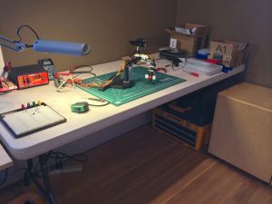
I’ve set up a workspace in my office using one of our folding tables from Costco.
The key reason for the space is simply so that I can leave projects in situ and resume them later with little to no setup or teardown. The table itself is not ideal. It’s plastic so the potential for static build up is very high. Need to either get some kind of grounded metal sheet to work off or purchase a more suitable workbench. For now it’s what I have on hand and I’m careful to ground myself regularly.
You can see the Rascal robotic arm sitting on the table. It’s made up of 6 servos. Still waiting for the servo shield I purchased for the Arduino Uno to arrive (and it will take even longer as I discovered that I had added items to my cart but had not proceeded to the checkout. Doh!). I do have some 555 timers, resistors, capacitors, a power supply and a potentiometer so my first real project was to create a simple servo controller.
Servos have three pins. One is the ground(-) and one is power(+). The third is the “signal” pin. It is used to control the position of the servo’s arm. The way to do this is to drive the pin high every 20 milliseconds for a duration of between 1 and 2 milliseconds. It’s the width of the pulse that is important. A width of 1.5 ms puts the servo into “neutral” position or 90° position. A width of 1 ms means 0° and 2 ms means 180°. I believe the actual frequency of the pulse does not have to be exact but 50 Hz should work for most standard servos.
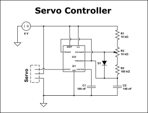
The following 555 circuit is what I ended up designing and building:
Made a lot of newbie mistakes while designing and building this circuit. It was very frustrating but it did drive me to thoroughly understand how the 555 timer works. Also had the added complication of missing a whole range of resistors from the resistor kit I had bought and only having a 10K Ω potentiometer to work with. Ended up creating a spreadsheet to calculate what combinations of resistor and capacitor values would work together. Also I wish I had an oscilloscope. It would have saved a lot of time.
Now, after figuring it all out and getting it working, I feel I can use the 555 to create any wave form with relative ease.


What is the value of the diode D1?
LikeLike
Do you mean the type of diode? Just a standard switching one. I’m pretty sure I used a 1N914.
LikeLike
Can you post spreadsheet to calculate what combinations of resistor and capacitor values would work together?
Thank you.
LikeLike
Unfortunately I no longer have the spread sheet. I might very well revisit the 555 timer in more detail as this post seems to get a lot of search hits. If I do then I’ll definitely create a spreadsheet or maybe even some kind of interactive widget. I’m definitely itching to get back into projects again after a long hiatus.
LikeLike